Normal lines inverted, holes and multiple shells
In this article, we will discuss the most common errors found in STL files, which usually involve inverted normals, presence of holes, and multiple shells.
These errors often result from mistakes during part modeling or during the export and conversion process to the STL file format using CAD software. These defects need to be corrected in order for the part to be suitable for printing.
As highlighted in the previous post, the STL file, necessary for 3D printing a part, represents a three-dimensional geometry composed of triangles oriented in space.
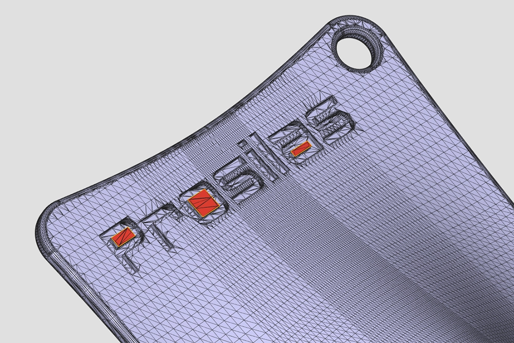
Normal line inverted
Each triangle is described not only by the coordinates of its vertices, but also by the normal, which is a vector perpendicular to the plane on which the triangle is positioned, and its orientation defines the outer side. In some cases, the normal of these triangles can be inverted, mistakenly identifying an outer side as the inner side and vice versa. Such a situation can lead to errors during the printing process.
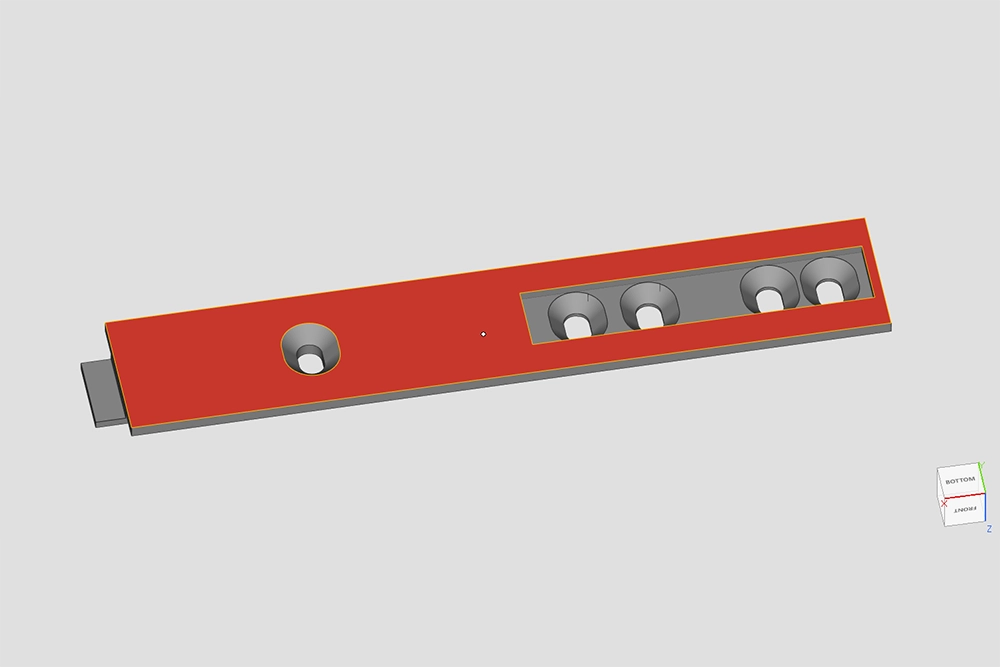
Example of a normal line inverted
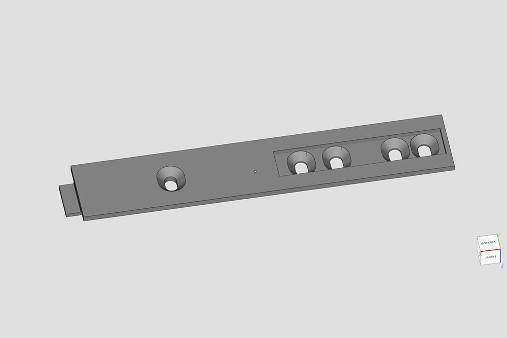
Example of a normal line corrected
Hole in the STL file
The second most common error encountered is the presence of holes, which can be caused by missing surfaces or misalignment between triangle vertices.
These holes need to be manually corrected if they are of considerable size, or automatically using specialized software if they are smaller. The presence of holes can compromise the quality and functionality of the printed part.
The presence of holes can compromise the quality and the realization of the part printing.
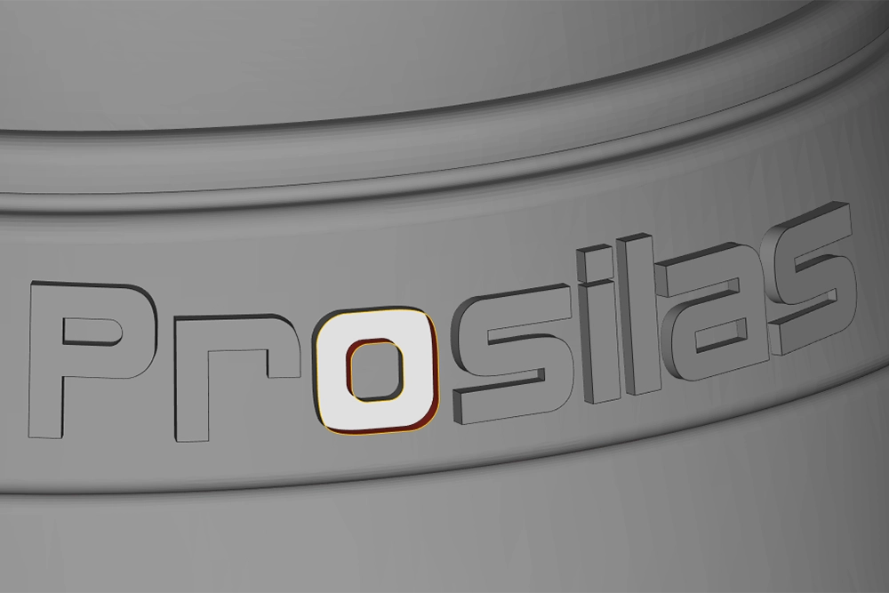
Holes in a STL file
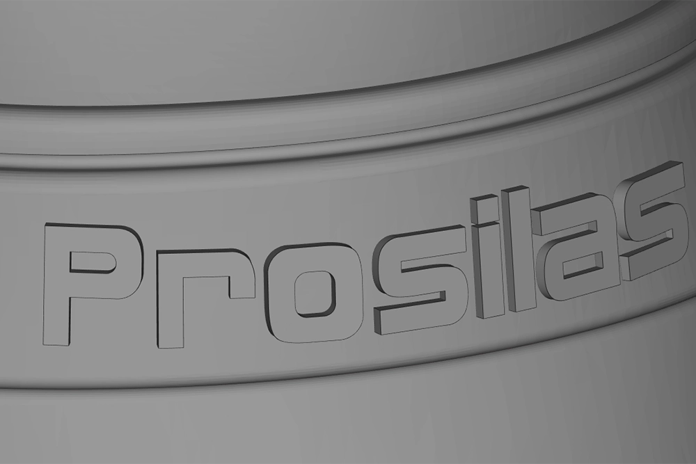
STL file corrected
Shell Multiple
Lastly, we encounter the issue of multiple shells. A shell refers to a group of connected triangles. The presence of multiple shells in a part indicates the presence of separate groups of triangles. In this case, the inner shell overlaps with the outer shell.
Resolving this type of error is necessary to avoid anomalies during the slicing of the model into layers or incorrect surface generation, as well as to prevent printer jams. It is important that all shells are properly joined to achieve a coherent and functional printed part.
This situation can also occur when, in the design phase, the shapes that make up the CAD model are not properly integrated into the rest of the shell, but remain separate.
It is crucial to ensure that all components of the model are correctly integrated into the main shell to avoid printing issues and ensure the quality of the final product.
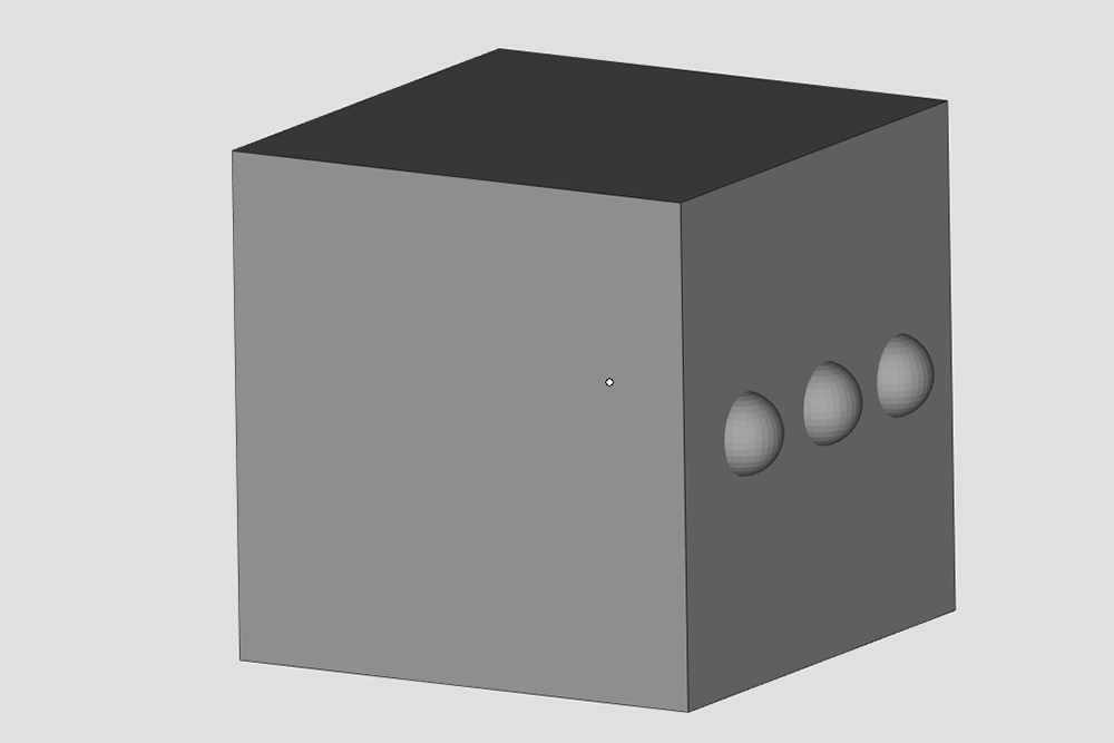
Example of Multiple shells
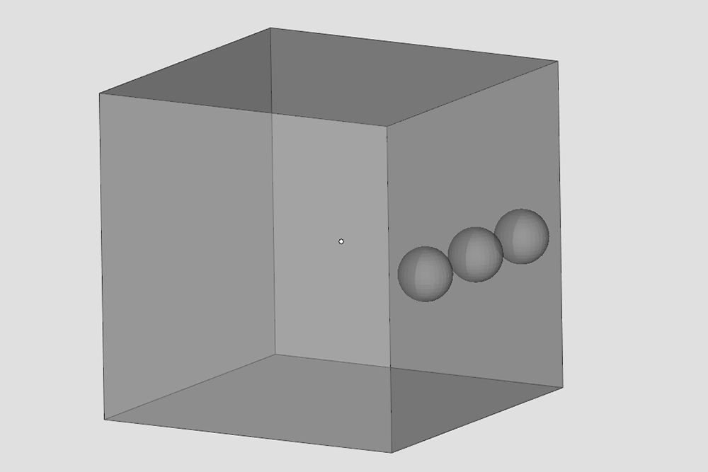
Example of Multiple shells
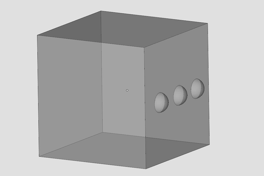
Multple shells fixed
When we receive the files. stl from our customers, it frequently occurs the need to make changes and corrections before proceeding with the production.
STL correction requires specific skills and the use of dedicated software to repair imperfections and ensure that the part is ready for printing.
Our team is fully committed to making such corrections with the utmost precision and timeliness, in order to ensure that the printed parts reach high quality standards and fully meet customer expectations.
